
We usually get asked the same questions over and over. So to stop my ear from being microwaved by the mobile phone, we have put this page together to answer some of the most frequently asked questions.
Hope it helps you out, if not we are still always on the other end of the phone or email!
Workshop: +44 (0)1304 814 447
Email: info@ooracing.com
Spark plug colour check
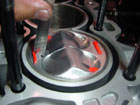
Look at the spark plug porcelin for the colour and condition of it. Plug colours tell us how the engine is running and can be very important. Plugs change colours and the different colours can explain such things as if the engine is running too hot or if the engine is worn. The colour should be read by looking at the porcelin insulator and compared to the plugs shown on the next few pictures.
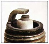
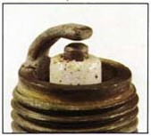
Normal: grey to light golden-brown colour. This condition is ideal, the spark plug and engine air/fuel mixture are operating properly.
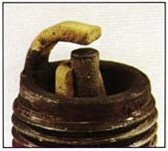
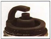 Dry Fouling: Black Soot Buildup.Air/fuel mixture is too rich, the carburettor settings are incorrect, spark plug heat range is too cold for the operating conditions. Ignition system problems causing a weak or intermittent spark.
 Wet Fouling: Shiny, Wet, Black Appearance. Excessive use of the choke (gas fouled). Prolonged low rpm operation (gas or oil fouled). Sign of damaged cylinder passing oil.
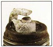
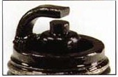
Excess Deposits: Bumpy, Chalky Buildup. Poor fuel quality. Oil leakage into combustion chamber. Improper oil used for premix/injected.
 Overheated: White, Blistered, Melted Electrode. Lean air/fuel mixture. Spark plug heat range is too hot for operating condition of the engine. Plug is not properly gapped and/or torqued onto head. Overly advanced timing
 Breakage: missing or damaged components of the spark plug. Caused by thermal expansion/ contraction of the insulator, typically due to thermal shock (the sudden increase or decrease in temperature). Sudden decreases in temperature can most commonly be coincided with entering a large pool of water while the engine is hot, or a broken water jacket for liquid-cooled engines.

Detonation: silver or black specs, melting or breakage at the firing tip. Caused by improper timing. Lean air/fuel mixture can aggravate this condition.
Carb Jetting and Adjustment top end
I can't stress how important it is to use GENUINE MIKUNI or KEIHIN jets in your carb. Aftermarket jets just aren't manufactured to the same tolerances and can vary quite a bit from OEM specs.
Most carb have three major circuits (some have more, some have less) to cover the tuning range:
An Idle Circuit.
A Mid-range Circut
A Wide Open Circut
These circuts overlap each other just a bit, so the transition between them is smooth and unnoticed.
Things such as atmospheric pressure, humidity, altitude and temperature all have effects on the tuning of a carb. The more modified an engine is, often - but not always the case - the more sensitive it may be to jetting. You'll find out by tinkering with your individual setup.
Starting with the Main Jet
The Main Jet only works on the upper end of the throttle - approximately 3/4ths to wide open.
Make sure you have a new spark plug installed.
Take your ride out and get it warmed up.
Run it full throttle, get it going as fast as it will go for a block or two and then hit the kill switch, close the throttle, put it in neutral and roll to a stop.
Pull out the plug.
What does your spark plug look like after a wide open throttle (WFO) run?
What color is the electrode? (the part that has the little tit sticking out of it under the little bar)
Is it black? If so, then it's rich. Drop the Main Jet size ONE
Is it white? Then it's lean. Raise the Main Jet size ONE
It should be about the color of a pancake or waffle.
For now, change Main Jet sizes in ONE STEP increments. (one size is not 150 to 151, it will jump say to a 152 or 153 - same the other way - prolly a 147 or something near that)
Go do a plug chop again. What does it look like now? If it's still white, then you're still lean, if it's still black or dark, then it's still rich. Change the Main Jet accordingly and go do the plug chop again. Keep it up until you end up with a nice brown plug.
Carb jetting at the bottom end of the range
 In general, a FOUR stroke carb has an Air Screw adjustment - which will be on the manifold side of the carb slide.
Most of the time, the air screw is set about 1-1/2 turns out from fully seated - this is a good base line starting point.
At first, adjust the Air Screw in 1/2 turn increments so you can see the difference. Then start being more finite by making 1/4 turn adjustments. You'll eventually get to where you only need to make adjustments in 1/8 turn increments.
Get your ride idling in neutral (warm it up fully first)
Quickly nail the throttle, going from idle to wide open in a smooth manner, but quick manner.
Just stabbing the throttle as fast as you can may cause enough disruption in the flow of the intake that the engine can't keep up - eventually, when the carb's tuned correctly, you should be able to nail it and have the engine react correctly. You'll see how this works as you tune the carb.
What does the engine do? Does it hesitate and then rev up? As it comes back down to idle, does it seem to hang at a higher idle for a minute and then settle down to normal idle?
If it does this you're too lean on the Air Screw adjustment. You need to richen it up by turning the Air Screw IN 1/2 turn and then repeat the test. Adjust as necessary, repeating the test until you have a nice response.
Or
Does it sound like it bogs a bit? As it comes back down to idle, does it seem to drop to a low idle (or even die) and then come back to normal? If it does this, it's Too Rich. Turn the Air Screw out 1/2 turn. Adjust as necessary, repeating the test until you have a nice response
Brakes/fluids
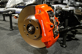
Brake fluid is hygroscopic (readily taking up and retaining moisture); it attracts water. This water is in the form of moisture in the air. Moisture in your braking system is very dangerous, as water boils faster than brake fluid and can lead to serious problems with the braking performance of your bike. It can also corrode parts of your brake system, including fittings, pistons and the master cylinder. Believe me, I can tell you from experience!
Use below links to easily navigate this page:
The benefits of gas flowing
The CDI unit
Spark plug colour check
Pulse coil
What is a three angle valve job
Squish band and deck height
Adjustable valve timing
Carb jetting
Carb jetting at the bottom end
Main Jet
LCA Valve timing
Valve to piston clearance
valve spring and guide clearance
set valve clearance
Tyre speed rating
The benefits of gas flowing
The cylinder head is where most of the performance benefits come from when modifying a head. Think about it. When you open the throttle, more power is produced. But you can only open the throttle to full and only so much can be produced.
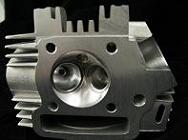 What is the restriction? Well, there are several on a standard engine. But, what if you have already put on larger throttle bodies, bigger carbs, a free flow exhaust, a new engine management system or a high lift camshaft? There is still a restriction, a limiting factor which prevents the engine from making even more power. This is where a gas flowed head comes in. You can add all the induction, exhaust and electronic control you want but if the head cannot flow more air and fuel it will be ultimately be limited in its performance. To raise this limit you need to improve the flow efficiency of the head.
The CDI unit
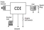 The CDI itself is really just an amplifying switch with time delay. It sits there storing up electricity in a capacitor (ie the "C" in "CDI"), then the pulse sensor spikes the input, the CDI waits a small amount of time and then puts the burst of electiricity it stored into the coil. That small amount of time represents the advance curve of an engine, ie at idle an engine may need 10 degrees advance but at full revs it may need 40 degrees advance. By delaying the signal and having the pulse sensor in the right place, the CDI can make sure the engine is getting the right advance curve.
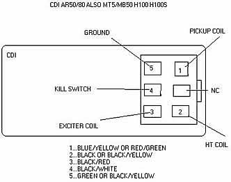
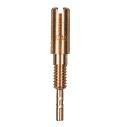
Pulse coil
Another coil, but only a small one. It too has a magnet spinning near it - but the magnet only passes by the coil once per revolution and it's a real small magnet. This means that most of the time there is not electricity flowing in the pulse sensor - but when the magnet passes by the coil you get a tiny spike of electricity. This tells the CDI to make a spark as the magnet is cunningly positioned so that the spike hits the CDI at just the right time. Make sure you have a 15 thou air gap.
What is a three angle valve job
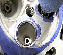 A three angle valve job has two more angles than a standard valve job. The benefit comes from one angle placed on top and the other placed on the bottom of the standard seat angle. This produces a curved effect so air and fuel will flow with less resistance. The result is better response and better performance.
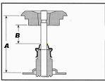
Squish Band & Deck Height
The Squish Band or "Quench" is defined as that area between the flat of the piston and the flat of the cylinder head at top dead center (TDC). On the compression stroke, as the piston approaches TDC, the compressed mixture of fuel and air is "squished" to the remaining space of the combustion chamber where the spark plug and valves reside. The "squeezing" of the mixture creates turbulence and is expected to promote a better and more complete combustion.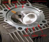
Typical figures for this measurement are in the range of .040" to.045" which allows for rod stretch, carbon build-up and other variables. The AC-5RR motors are designed with .035" squish to accelerate the turbulence and to further concentrate the mixture in the remaining combustion chamber while leaving a small margin for carbon build-up. Pure race engines with short duration applications may reduce this figure to .025" as some builders aren't happy till the pistons "kiss" the cylinder head. At .025" when you factor in high rpm rod stretch and piston "rock" at TDC you effectively reduce squish to zero.
It's a simple fact: The closer the flat of the piston to the flat of the combustion chamber, the more power you will make. In a race engine with all the factors considered you practically want the two surfaces touching one another. In F1 they machine each piston individually even for the spark plug relief..
Deck Height: The distance between the flat "quench" surface of the piston and the top of the bare cylinder (no head gasket). Typically an engine is set to zero deck height with the head gasket (compressed value) defining the "squish band" value. If the value is negative this indicates the piston's "quench" surface extends above the top of the bare cylinder
Adjustable valve timing
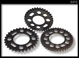 Modification of an engine’s valve timing is best approached with a degree of caution. For otherwise stock engines, the mildest cams should perform well. Performance will improve with improved induction, i.e., carburetion or a more efficient injection (ported/polished throttle body) and exhaust system (headers). Modest performance increases can always be achieved by fine turning with adjustable timing gears to advance or retard the valve opening and closing.
LCA valve timing
 The easiest way of timing camshafts is by using the lobe centre angle (LCA) method. This involves setting the engine on true TDC which makes the full lift position for no. 1 inlet, the LCA after TDC and on no. 1 exhaust the LCA before TDC there will be a dwell on full lift. The true position is in the centre of this dwell.
Valve to piston clearance
 On 4 cylinder engines the inlet should have .050" at 10 deg after TDC and the exhaust .065" clearance at 10 deg before TDC. On single cylinder engines the inlet should have .080" clearance at 12 deg after TDC and the exhaust .080" clearance at 12 deg before TDC.
Valve spring and guide clearance
 Valve spring clearance should be a minimum of .040" before coil bind. Valve cap to valve guide clearance should also be a minimum of .040".
Set valve clearances on pit bikes/monkeys
We recommend to set the valve clearance to .004" inlet and .006" exhaust for optimal range.
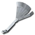 Remove generator cover, valve caps and spark plug. Turn the engine to the T mark, watching the rockers. If they are rocking on the T mark, turn the engine another 360 deg to the T mark. This is the firing stroke. Undo the locknut on the inlet rocker. Wind out adjuster. Put the feeler gauge in between adjuster and valve. Wind down the adjuster to the point of contact, back off quarter of a turn, and tighten locknut. Check resistance on feeler gauge and repeat process for exhaust.
Tyre speed rating
Maximum Design/Test Speed
- "J" Type 62 MPH
- "N" Type 87 MPH
- "P" Type 94 MPH
- "S" Type 112 MPH
- "H" Type 130 MPH
- "V" Type 149 MPH
- "Z" Type 149+ mph
Tyres with 2.00, 2.25 & 2.50 nominal section widths are rated for 75 mph.
Registration chart
You can use the charts below to quickly identify the original year of issue for the three main registration formats.
A 1963 A 1983
B 1964 B 1984
C 1965 C 1985
D 1966 D 1986
E 1967 E 1987
F 1967 F 1988
G 1968 G 1989
H 1969 H 1990
J 1970 J 1991
K 1971 K 1992
L 1972 L 1993
M 1973 M 1994
N 1974 N 1995
P 1975 P 1996
R 1976 R 1997
S 1977 S 1998
T 1978 T 1999
V 1979 V 1999
W 1980 W 2000
X 1981 X 2000
Y 1982 Y 2001
DIGITS YEAR OF RELEASE
00 NEVER RELEASED
01 NEVER RELEASED
51 2001 Second Half
02 2002 First Half
52 2002 Second Half
03 2003 First Half
53 2003 Second Half
04 2004 First Half
54 2004 Second Half
05 2005 First Half
55 2005 Second Half
06 2006 First Half
56 2006 Second Half
UK Office: +44 (0) 1304 814447 • E-mail: info@OORacing.com
Home :
Performance Products :
Workshop Services :
Starforce Race Bikes :
About Us :
Credits & Links :
Tuning Tips
©2006 Mortimers of Canterbury
Site by Mpjdesign